Deconstructing the Sine Quadrant-Part 2: The Advanced Functions
- on 02.03.14
- Random Jottings, Sine Quadrant
- Comments Off on Deconstructing the Sine Quadrant-Part 2: The Advanced Functions
In the previous post, I described the basic features of the Sine Quadrant, and described two of its most common functions: measuring angles and converting back and forth from angle to sine/cosine.
[If you need it, here is a link to the PDF of the example sine quadrant you can print out to follow along.]
In this and subsequent posts I will start to dig deeper, and examine the function of some of the other markings on the face of a typical sine quadrant.
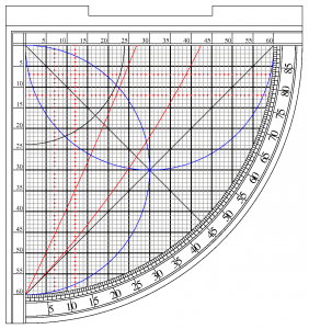
The reader is now familiar with the sine/cosine grid and its uses, but a close examination of the face of our example sine quadrant shows several lines and arcs we have not yet discussed.
The Sine and Cosine Arcs
On many sine quadrants there will be two half-circle arcs (blue on the figure above), one centered on the Sine scale, one centered on the Cosine scale. These can be used in conjuction with the Sine and Cosine scales as an alternative method of converting angles to sine/cosine.
Note: If these arcs are to be used, there has to be a moveable bead on the weighted cord, this bead is used as a cursor to mark a position on the cord. Think of it as memory storage for the device.
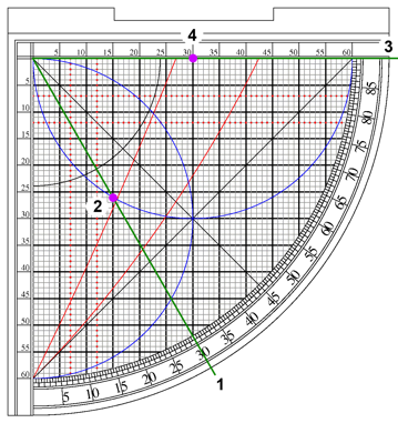
To use these arcs, the procedure is similar to using the grid. First the user pulls the cord taught over the desired angle. Next, the user slides the index bead to rest directly on the appropriate arc (the horizontal arc for sine, the vertical for cosine). Once the marker is in place, the user will then rotate the cord to the sine or cosine scale and read the answer from the point under the bead.
In the figure below the cord is first set to 30 degrees(1), the bead is then positioned directly on the sine arc(2), then the cord is rotated to the horizontal sine scale(3) and the sine is read(4) as 30/60 or 0.5.
Converting to other way, from sin/cosine back to an angle is straightforward as well the user just lines the cord up with the scale, positions the bead at the given sine or cosine; then rotates the cord until the bead touches the appropriate arc. Then the cord will be set to the equivalent angle.

