The Future: Moving the Astrolabe Generator away from Flex

I like Flex, but the tools to use it are not cheap. I can’t afford $250+ for the next version of Flash Builder and from what I’m seeing even Adobe is jumping on the HTML5 bandwagon. If Adobe offered a free, noncommercial version of Flash Builder, I might be convinced to stay with the platform. but I’m not seeing a future for Flex/Flash and the open-source community is not embracing it.

I’ve looked at HTML5, and it has potential, but it suffers from the same problem all the previous versions of HTML/JavaScript suffered from: uneven browser support. I don’t want to have to rewrite my interface code for every browser version that comes along. That got old years ago. I looked at other options as well, but Java is still the best choice I can find: It is object oriented, strongly typed, open source, platform independent, and has a massive list of free and open source tools to work with it.

The conversion will take time, But I’m planning on releasing the java version as 4.0 in the Fall. If anyone wants to jump on the bandwagon, contact me and I’ll send you my notes on the overhaul. As always, the code is checked in at SourceForge[http://sourceforge.net/projects/astrolabegenera/].

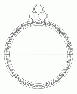
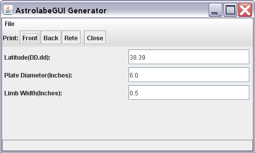
While I was digging through the process of planning the new version, I set up and ran the original java project:

Version .5 of the Astrolabe Generator

I’ve made a bit of progress since then.

The Future: Version 3 of the Astrolabe Generator

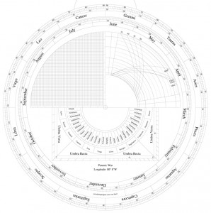
I spent most of the last weekend coding like crazy. I now have three new optional scales to add to the back of the astrolabe:Preview of Version 3 of the Astrolabe Generator

The Lunar Mansions. A calendar/astrology scale. This is visible inside the shadow squares, center bottom.

Two views of the Arcs of the signs: Equal sized and projected(top left shows the projected view of the arcs, with the Noon lines and the Qibla lines)

These are still not ready for use(note the missing labels…), but I’m planning on finishing them for the 3.0 release later this spring.

Drafting the Astrolabe 7: The Calendar Scale.

The next step in drafting the astrolabe is constructing the calendar scale.

Up until now the process of creating scales has been straightforward. The time scale on the front and the altitude and zodiac scales on the back are simple in concept and execution, requiring no math to draw. The calendar scale, on the other hand, needs to be aligned to the zodiac scale so that when the alidade pointer is rotated to a given date, the pointer crosses the zodiac scale at the Sun’s ecliptic position on that date. This is not straightforward, as the Earth’s orbit is elliptical, and the Sun appears to move along the ecliptic at different speeds at different times of the year; in other words, it covers a slightly wider arc per day in winter than in summer.

Traditionally, there are two ways to allow for the Sun’s uneven motion. The first is the concentric method, where the calendar circles are drawn concentrically with the zodiac circles. In this case the days are drawn on the scale so that the space between the day marks varies depending on where on the scale they are. To accomplish this, the astrolabe maker must determine the exact location of the Sun for each day. This method requires a lot of careful calculation and measurement, and would be very time-consuming, unless reference tables are available. I could use this method, as I have access to an accurate ephemeris. But the drawing of the day lines would be more finicky that I would like to attempt for a first try.

The second, simpler method is the one I’m going to use. This second method, the eccentric method, offsets the center of the calendar scale from the center of the zodiac scale, modeling the offset of Earth’s orbit. This method is actually very accurate, well within the overall accuracy of the astrolabe itself [Morrison: 111] and was used extensively by astrolabe makers. To accomplish the drafting this scale accurately, three factors must be known in advance: The direction of the offset, the distance of the offset, and the rotation of the calendar.

First, direction; from Stoeffler:

Find the Apogee of the Sun, corresponding to the time of construction of our astrolabe through the Alfonsine Tables, or through other tables. For example, in the Year of Christ 1510, with exact calculations, it is around 1 degree 16 minutes of Cancer. Therefore, get ready to place it on this point of Cancer, as this is its position in the year mentioned, that is, at the 16th minute of the second degree of Cancer.” [Stoeffler: 66]

The Alfonsine Tables {http://en.wikipedia.org/wiki/Alfonsine_tables} and other tables mentioned are tables of astronomical data that would have been expected to be available to someone designing astronomical instruments of the period.

Lacking such tables, I will have to do some computation. Morrison goes deeply into the math in his section on drawing the eccentric calendar; so I won’t try to duplicate his work in detail here, if you are interested I recommend his book very much. Here is a summary of the process:

Step 1. Compute the Julian Century (T)

The Julian Day for January 1, 2000 at noon UT is 2451545.0 [after Morrison: 337].

The current Julian Day (For the time of writing (November 14, 2011), is 2455879.5).

The Julian Century is computed as follows:

T = (2455879.5 – 2451545.0) / 36525 = 0.118672142 [after Morrison: 337].

Step 2. Find the angle of perihelion (Q)

Q = 102.937348 + (1.7195269*T) + (0.00045962*T^2) + (0.000000499*T^3) = 103.1414144 [after Morrison: 112].

Or 103 degrees rounded off. Counting around counterclockwise from Aries 0, this gives me an angle of Cancer 13.

Next, I need to know the magnitude of the offset. Stoeffler gives an offset of 1/32nd of the inner radius of the zodiac ring (0.03125 x R) [Stoeffler: 67]; where Morrison computes it to be 0.0334 x R [Morrison: 112]. Morrison is definitely the more accurate; but as the difference is about a hundredth of an inch for the circle I’ll be drawing, I’ll go with Stoeffler, as it is easier to draft.

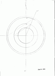
With these first two factors known I can draw the rings for the calendar. The procedure is as follows (See the figure to the right):

A. Find the center of the zodiac ring. This is, of course already marked; I used it to draw the zodiac circles.

B. Draw a construction line (to be erased later) from the center to the inside edge of the zodiac ring at an angle of 103 degrees from Aries 0 (to Cancer 13).

C. Divide this line repeatedly until you have a mark 1/32 of the way from the center to the edge (exaggerated here).

D. Using that point as a center, draw the circles for the calendar ring.

Finally, I need to know where to start drawing the calendar; that is, how to rotate the calendar so that it is properly aligned with the zodiac.

Stoeffler calls for aligning the beginning of January with Capricorn 20:

Make the subdivisions of the days and of the months in this way. Set the rule on the center E and on the 20th degree of Capricorn and draw a line segment crossing all the eccentric circles. It will point out the beginning of January and be marked with a G. Starting from it, in the opposite direction to the succession of the Signs, count around 5 degrees 20 minutes. Set the rule between this point and the center E. Draw a line from the first eccentric circle to the second, which will be H. The remaining arc must now be divided (this small arc excepted) into 360 equal parts…” [Stoeffler: 67]

The sky has shifted a bit in 500 years. Using the equations in Morrison’s book, I come up with a rotation figure of -79.4757 (call it -79.5 degrees). Starting from Aries 0 and counting clockwise (remember, the sun moves counterclockwise through the zodiac ring, and we are rotating backwards) that puts the line for the beginning of January at Capricorn 10.5.

I now have all the figures I need to begin drafting the Calendar Ring.
Drafting the Astrolabe 6: The Zodiac Scale

OK, yes, that was tedious. But now it is done.

I have started work on the back of the astrolabe: The first scale, the zodiac ring, is finished.

Drawing this used a combination of geometric construction and fudging with the compass. First, draw the outside edge of the astrolabe (set the compass using the finished front drawing). When this is done draw 4 more circles of diminishing radius to make the scale. Then trisect the four quadrants. This divides the scale into the twelve astrological signs. Fudge with the compass to divide each sign into three parts, giving you the ten-degree marks. Then next, bisect the 10-degree angles to give the five-degree marks. Finally manually divide each five degree section into five one-degree ticks.

The Back of the Astrolabe

The scales should be marked as follows: The top half of the outermost ring should be marked 0-90 degrees on each side (zero for the horizontal and counting up to 90 for the vertical). This is the elevation scale, used to measure elevation above the horizon.

The innermost scale needs to be marked with the zodiac (I used the symbols, but spelling the names out is also used): Starting with Ares on the right side above the horizontal line and working counter-clockwise through the rest of the zodiac in order. Finally, each zodiac section has to have the 10 and 20 degree ticks marked (note that these are marked counter-clockwise as well).

Next up: Adding the Calendar.

Drafting the Astrolabe 5: A Recipe for Fudge(ing)

The next big chore will be creating the major scales for the back of the astrolabe. This will involve drawing one set of rings representing the Zodiac and another set representing the Calendar.
Drafting the zodiac is straight-forward, if tedious. The circle needs to divided into 360  one-degree ticks. The process is the same one I used to create my protractor (link).
The next step will be -um- interesting. The calendar scale sits inside the zodiac ring and is oriented such that when placed on a date, the adidade pointer will also point to the position of the sun on the zodiac for that date. Unfortunately, where 360 divides up well, 365 does not. in fact, the only divisors other the 1 and itself are 5 and 73. Now I can divide the circle into 5 equal parts (quintrants?)by cheating with the compass, but after that 73 is prime and not divisible equally. In addition the year is not 365 days…. it is 365.25.
So I looked at my sources. Stoeffler has this to say:
“Make the subdivisions of the days and of the months in this way. Set the rule on the center E and on the 20th degree of Capricorn and draw a line segment crossing all the eccentric circles. It will point out the beginning of January and be marked with a G. Starting from it, in the opposite direction to the succession of the Signs, count around 5 degrees 20 minutes. Set the rule between this point and the center E. Draw a line from the first eccentric circle to the second, which will be H. The remaining arc must now be divided (this small arc excepted) into 360 equal parts…”(Stoeffler:67)
Hummm. Clever.
So I am to remove the angle equivalent of 5.25 days from the circle, and divide the remaining arc into 360 ticks. Much easier. Or rather somewhat easier; as the 360-day section of the circle is NOT 360 degrees, I will not be able to quarter it and trisect etc. like I will the zodiac. I will need to bisect repeatedly and do some fudging with the compass when I need to divide an angle other than in half.
Question: Am I dividing into 365 or 365.25?
It occurs to me that at the finished diameter of my astrolabe, the .25 day tick will be approximately the same as the width of the line used to mark it. If I remove the .25 and use 365 ticks, each tick will be thrown off a bit: By approximately .0007 of the width of the space. This is not going to be measurable with this instrument.
An examination of the backs of several period astrolabes shows that leaving out the .25 is a regular practice. In fact, going back to Stoeffler: “The GH arc will be divided into 5 parts and 1/4, if it is held to precision” (Stoeffler:67). So for this project I’ll go with 365 days.

Drafting the Astrolabe 4: The Front

Back to work on this project:

I got several tasks done today.

When I am finished drafting my astrolabe, I plan on photocopying it onto card stock, and assembling and laminating it in order to compare it’s accuracy to a computer-generated version. I tested the photocopy process today.

First, I printed out the front of the computer-generated version of the astrolabe and then photocopied the printout. Then I measured the two with my point-scaled ruler (Note: PostScript measures in points: 1/72 of an inch).

The printed out version is a uniform 503 points in diameter, horizontally, vertically and obliquely (45 degrees). The photocopied version is 501 points horizontally and vertically, and 504(!) obliquely. Obviously my home photocopier is distorting the image a bit. If the hand-drawn version is going to be distorted for testing, it will skew the results.

Two possible options suggest themselves:

1. Test other, commercial, photocopiers for distortion an see if I can use them instead.

2. For testing, photocopy the computer generated version as well. If the distortion is uniform, as I suspect it will be, it will be the same for both test and control.

Next I got out the drawing tools and drew up a template for the climate plates. The three tropic rings will be the same for each plate, so constructing them each time is a waste of effort. The compass can instead be set from the template and the rings transferred to the individual climate sheets.

Template for the construction of astrolabe climates

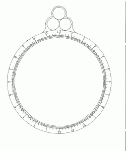
Next. I drafted up the front of the mater. First I drew a line down the center of the paper. then erected an perpendicular bisecting line using Method 1. I then transferred the lines for the inner and out edges of the mater limb from the printout of the computer generated example, to the paper using the compass. Four additional circles were drawn between these two circles to mark the various lengths of tick marks for the time scale.

The limb is to be marked in hours, half hours, quarter hours and five-minute ticks. To accomplish this I then used Method 6 to trisect the 4 quadrants, dividing the limb into 12 two-hour sections. I then bisected (Method 5) the angles giving me 24 one-hour sections. These 24 sections I marked across all four scale lines. I then again bisected the hour angles into half hours, and marked these across 3 rings. Bisecting again gave me my quarter-hour lines. marked over two rings.

Finally I abandoned the compass and straight-edge and eyeballed the division of the quarter=hour sections into three 5-minute sections (marked over two lines). I cleaned up the result by erasing most of the construction lines; and I inked the result carefully with a 0.1 mm drafting pen.

Front of the astrolabe mater,
The result is not the prettiest thing I’ve seen. But I’m not an artist. It does appear to be useable, however.
Next: Drafting the zodiac scale on the back.
Note: For methods of construction used see post: Drafting the Astrolabe: 2. Methods of geometric construction

Astrolabe Generator: Done For Now

I have just uploaded the last tweak I’m planning on making to version 2 of the Astrolabe Generator. I’ve done a lot of work on it over the last few weeks, and I’m happy with the results. I will still be planning to add more scales and functionality in the future, but it is time to shift my focus to other parts of the project…

I spent part of today going over the sadly neglected Astrolabe Manual. I’ll be working on that during most of my spare time for the next few weeks, so keep stopping back for updates, or subscribe to the RSS feed (See the link on the right).

In addition, I’ll be doing more work on the Astrolabe Drafting project. I think I have a good idea of what scales and detail I want to include now. More importantly, I can now use the Astrolabe Generator to print out a computer generated version of my design so I can compare accuracy.

So no more updates to the generator for a while, but more work on the other aspects of the Astrolabe Project.

If there is anything you would like to suggest to improve the site, bugs to report, functionality to add, etc. I’m posting an email address in the links menu.


Added a Horizons Plate

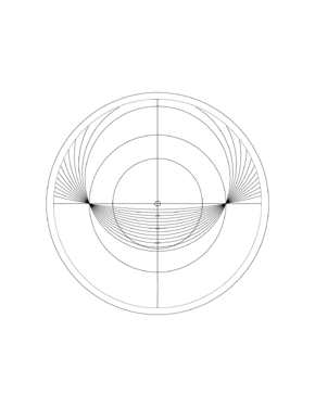
I did some doodling today and added a Horizon Plate to the Astrolabe Generator options.Astrolabe horizons plate

The plate covers latitudes from 10 degrees to 70 degrees in 5 degree intervals. This allows more portability for the astrolabe, at a cost of some of the functionality.

Astrolabe Generator Update (minor)

I updated the thumbnail graphics to make them easier to see.

Astrolabe Generator Update

I have added new more features to the Astrolabe Generator (http://astrolabeproject.com/build/). There is now a front degree scale option and I have added a new set of limb markings: Alphabetical (based on a 1370 astrolabe shown here).